English
- English
- Esperanto
- Afrikaans
- Català
- שפה עברית
- Cymraeg
- Galego
- Latviešu
- icelandic
- ייִדיש
- беларускі
- Hrvatski
- Kreyòl ayisyen
- Shqiptar
- Malti
- lugha ya Kiswahili
- አማርኛ
- Bosanski
- Frysk
- ភាសាខ្មែរ
- ქართული
- ગુજરાતી
- Hausa
- Кыргыз тили
- ಕನ್ನಡ
- Corsa
- Kurdî
- മലയാളം
- Maori
- Монгол хэл
- Hmong
- IsiXhosa
- Zulu
- Yoruba
- অসমীয়া
- ଓଡିଆ
- Punjabi
- پښتو
- Chichewa
- Samoa
- Sesotho
- සිංහල
- Gàidhlig
- Cebuano
- Somali
- Тоҷикӣ
- O'zbek
- Hawaiian
- سنڌي
- Shinra
- Հայերեն
- Igbo
- Sundanese
- Lëtzebuergesch
- Malagasy
- Español
- Português
- русский
- Français
- 日本語
- Deutsch
- tiếng Việt
- Italiano
- Nederlands
- ภาษาไทย
- Polski
- 한국어
- Svenska
- magyar
- Malay
- বাংলা ভাষার
- Dansk
- Suomi
- हिन्दी
- Pilipino
- Türkçe
- Gaeilge
- العربية
- Indonesia
- Norsk
- تمل
- český
- ελληνικά
- український
- Javanese
- فارسی
- தமிழ்
- తెలుగు
- नेपाली
- Burmese
- български
- ລາວ
- Latine
- Қазақша
- Euskal
- Azərbaycan
- Slovenský jazyk
- Македонски
- Lietuvos
- Eesti Keel
- Română
- Slovenski
- मराठी
- Srpski језик

On-Site Steel Structure Assembly + Integral Hoisting Construction Workflow + Key Considerations
Introduction: In steel structure construction, "ground assembly + heavy-crane integral hoisting" (assembling the structure completely on the ground and lifting it into position as a single unit using heavy cranes) is one of the most cost-effective, safe, and quality-controlled construction methods available today.
Compared with "high-altitude loose assembly" (assembling components piece by piece high in the air), this method significantly reduces hazardous work at height, lowers welding defect rates, and effectively controls structural deformation. However, it requires strict ground site preparation, high-precision assembly jig setup, rigorous lifting engineering calculations, and flawless on-site signaling and command.
Below is a comprehensive and standardized technical guide for on-site steel structure assembly and integral hoisting—structured with clear workflows and practical, straightforward technical requirements for easy reference.
I. Core Overview of the Construction Method
Construction Workflow Logic: Factory prefabrication of steel components in sections → On-site ground assembly on jigs → Welding correction, weld inspection (NDT) & paint touch-up → One-piece integral hoisting into position → Fixing and structural alignment.
Key Advantages
• Ground-Based Work Throughout: Primary operations are performed on the ground, drastically reducing fall risks and high-altitude hazards.
• Controllable Quality: Assembly, welding, and alignment take place in a stable, accessible ground environment, ensuring superior precision and build quality.
• High Construction Efficiency: High-altitude welding and bolting are minimized, significantly speeding up construction progress.
Limitations
• Large Assembly Area Required: Requires a spacious, level, and well-compacted ground area for on-site assembly.
• Heavy Equipment & Strict Checks: Requires high-tonnage lifting cranes and strict engineering calculations for lifting conditions and soil load-bearing capacity.
Applicable Scenarios
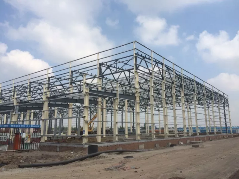
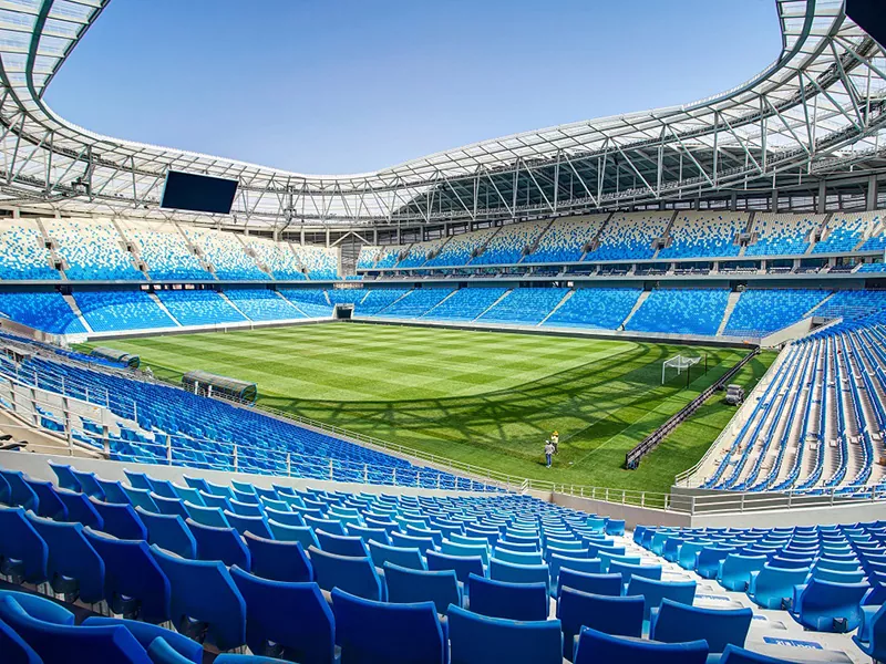
Open-site steel structure construction, such as large-span steel trusses, roof steel modules, multi-span steel frames, and heavy-duty crane girder assemblies.
II. Complete Standardized Construction Workflow
Standard Process Flow: Construction Preparation → Site Leveling & Compaction → Assembly Jig Setup & Acceptance → Component Receiving & Re-inspection → Ground Assembly → Welding Works → Weld Testing (NDT) & Anti-Corrosion Paint Touch-up → Lifting Lug & Rigging Setup → Trial Lift Test → Formal Integral Hoisting → Positioning Fine-Adjustment & Temporary Fixing → Re-checking Grid Axes & Elevation → Permanent Connection & Fastening → Rigging Removal → Project Acceptance → Assembly Jig Dismantling
1. Early-Stage Construction Preparation (Most Critical Step)
If preliminary preparation is inadequate, issues such as structural deformation, overturning, or dimensional errors can easily occur during assembly and lifting. Focus strictly on these 4 core tasks:
• Plan First: Prepare a dedicated hoisting scheme. For high-risk, super-critical operations, expert review and formal approval are mandatory. Complete detailed engineering calculations for crane operating conditions, member stress, ground bearing capacity, and lifting point loads.
• Material & Document Verification: Inspect factory certificates of conformity, mill test reports (MTR), factory non-destructive testing (NDT) records, and dimensional verification sheets. Strictly prevent any non-conforming components from entering the job site.
• Site Layout Planning: Clearly designate separate zones for component storage, ground assembly work, and crane travel/outrigger positioning. For soft soil foundations, excavate and replace with solid backfill, compact, and pave/harden the ground in advance.
• Personnel Safety Briefing: Welders, crane operators, signalers, and riggers must hold valid qualification certificates. Conduct thorough safety and technical briefings for all workers, clarifying individual responsibilities and safety prohibitions.
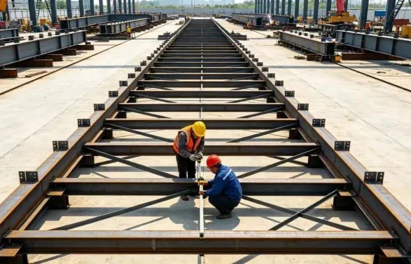
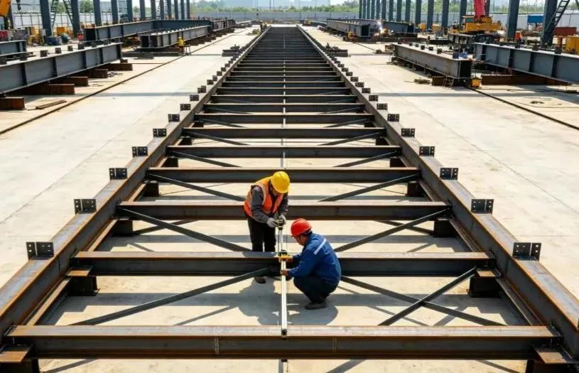
2. Assembly Jig Setup and Acceptance
The assembly jig (ground support frame) is essential for assembly precision. Casual assembly or substandard, makeshift frameworks are strictly forbidden!
• Use Standard Structural Steel: Fabricate jigs using national standard steel sections to ensure adequate rigidity and stability, preventing ground settlement, structural deflection, or shaking after loading.
• Precise Setting-out and Positioning: Accurately lay out guide lines; strictly control grid axes, elevation, and levelness. For large-span components, build in pre-camber (an intentional upward curve) according to design specifications to counteract future sagging under service loads.
• Dedicated Inspection & Sign-off: A specialized inspection must be conducted upon completion of jig setup. Record and archive all dimensional, elevation, and flatness measurements. The jig can only be used after formal sign-off
3. Component Delivery and Ground Assembly
Ground assembly is the key process for controlling overall structural quality. Precise control is essential:
• Inbound Component Inspection: Inspect each component upon arrival for appearance, shipping deformation, protective coatings, and bolt hole alignment. Straighten and correct any minor deformations prior to assembly.
• Jig Positioning & Adjustment: After seating components onto the jig, use hydraulic jacks and guy cables to fine-tune and strictly control span, axis lines, elevation, root gap (joint fit-up gap), and vertical alignment.
• Tack Welding by Certified Welders: Certified welders must perform tack welding (temporary holding welds). The tack weld length and fillet leg size must meet technical standards, preventing porosity, cracks, and other welding flaws.
• Symmetrical Welding & Stress Relief: Formal welding must strictly follow the principles of "symmetrical welding" and "back-step welding" (welding in short alternating segments) to evenly release thermal stress and minimize warping. For thick steel plates, strictly implement preheating and interpass temperature controls.
• Post-Assembly Verification: After assembly is complete, thoroughly re-measure overall dimensions, camber values, and lateral straightness to guarantee full compliance with engineering codes and design drawings.
4. Weld Inspection and Anti-Corrosion Paint Touch-up
• Non-Destructive Testing (NDT): Perform Ultrasonic Testing (UT) or Radiographic Testing (RT) per design specifications. Any non-compliant weld must be completely gouged out, re-welded, and re-tested until 100% qualified.
• Weld Cleaning & Repainting: Grind welded joints smooth, remove rust, slag, and spatter, and promptly apply matching anti-corrosion primer and topcoat to ensure a continuous and intact protective coating system.
• Surface Protection: Protect high-strength bolt friction contact surfaces, bolt holes, and finished paint layers from weld spatter, grease/oil contamination, and mechanical scratches.
5. Lifting Points and Rigging Selection
Core Lifting Safety Rule: Never change lifting points without authorization, never mix mismatched rigging, and never subject components to improper forces.
• Use Designed Lifting Lugs: Always use pre-designed, factory-engineered lifting lugs (pad eyes). Unapproved on-site welding or hole drilling for makeshift lifting points is strictly prohibited. All lifting lug welds must undergo 100% NDT inspection.
• Rigging Capacity Calculation: Select steel wire ropes, shackles, and lifting slings strictly based on calculated loads, incorporating dynamic load safety factors. Overloading is strictly prohibited.
• Corner Protectors: Install corner protectors (softeners/edge guards) at all sharp corners and edges of the steel members to prevent wire ropes from being cut or damaged.
• Temporary Reinforcement: Add temporary bracing struts/members to structurally slender or thin-walled sections (such as long trusses) to prevent twisting, buckling, or local deformation during hoisting.
6. Trial Lift Test (Must Never Be Skipped)
The trial lift is the final defensive barrier against hoisting accidents.
• Lift and Hover: Smoothly hoist the component 200–300 mm clear of the assembly jig, and hold it suspended in the air for 5 to 10 minutes.
• Comprehensive Inspection: Thoroughly inspect: load conditions at lifting points, rigging deformation, overall and local member deflection, crane stability, ground settlement under outriggers, and any interference or snagging on the jig.
• Immediate Lowering on Abnormality: If any unusual noise, structural distortion, or excessive ground settlement is observed, lower the component back onto the jig immediately. Formal hoisting may only proceed after corrective actions are approved.
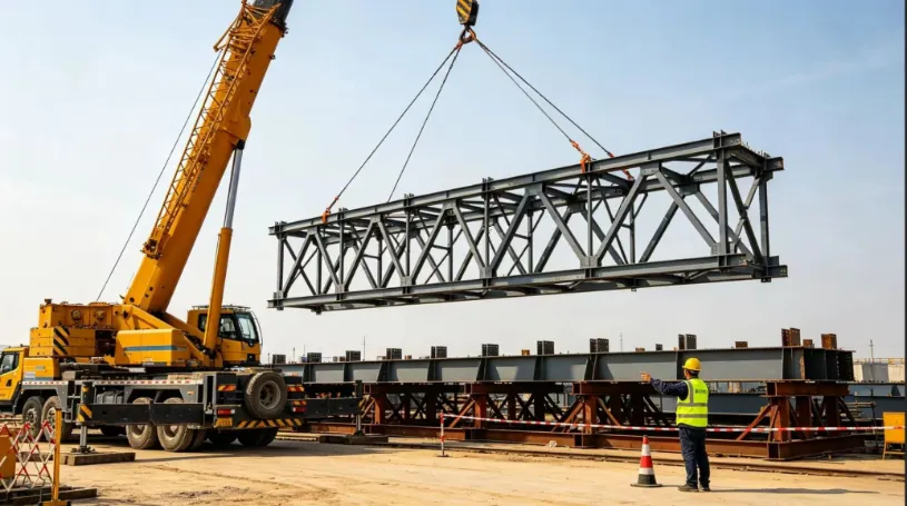
7. Full-Assembly Hoisting, Positioning, and Temporary Securing
• Unified Single-Person Signaling: Operations must be directed by a single appointed signaling commander using standardized hand signals and voice commands. Multiple-person signaling and chaotic operations are strictly prohibited.
• Smooth Crane Movements: Hoisting, slewing (swinging), and luffing (boom derricking) must remain smooth and slow throughout. Avoid abrupt stops, sharp turns, or shock loads. Ground crew must use tag lines (guide ropes) to stabilize the component's orientation and prevent collision with existing structures.
• Positioning & Immediate Temporary Support: Once seated onto the permanent supports, precisely fine-tune grid axes, elevation, and vertical plumbness. Immediately install temporary support struts and tighten guy cables.
• Core Safety Red Line: Never release the crane hook until the steel structure forms a stable, self-supporting structural system.
8. Permanent Connection and Finishing Works
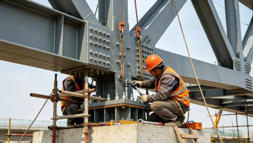
• High-Strength Bolting First: Prioritize high-strength bolt fastening. Strictly follow the two-stage tightening sequence: "Initial Tightening → Final Torque Tightening". Mark each bolt clearly after final tightening to prevent missed, loose, or over-torqued bolts.
• On-Site Splice Welding: Perform on-site butt and splice welds in multi-pass layers, and conduct non-destructive testing (NDT) promptly upon completion.
• Overall Structural Re-measurement: Re-measure all overall dimensions, elevations, and deflection values. Once certified as compliant, safely dismantle lifting gear, temporary supports, and the ground assembly jig.
• Coating Repair & Handover: Touch up all damaged anti-corrosion and fireproof coatings across affected areas to complete the finished installation.
III. Critical On-Site Precautions (Key Pitfalls to Avoid)
1. Assembly Quality Control Points
• Solid Jig Foundation: The ground beneath the assembly jig must be firm, compacted, and level. Assembly work is strictly forbidden on soft soil or waterlogged ground during rainy weather to prevent uneven settlement.
• Strict Pre-camber Control: Accurately set the pre-camber (intentional upward curve) for large-span members according to design values. Double-check measurements before and after assembly to prevent downward sagging after erection.
• Severe Weather Welding Restrictions: Immediately cease open-air welding during strong winds, rain, snow, or freezing temperatures. Ensure damp steel surfaces are thoroughly dried with heating torches before resuming welding.
• Protect High-Strength Bolt Friction Surfaces: Strictly protect bolt contact friction surfaces. Grinding, oil contamination, or weld spatter burns are strictly forbidden, ensuring the slip coefficient meets engineering standards.
2. Mandatory Lifting Safety Red Lines
• Weather Prohibitions: Hoisting is strictly forbidden during strong winds of Force 6 and above (wind speed ≥ 10.8 m/s), dense fog, heavy rain, or when night lighting is inadequate.
• Crane Outrigger Support: Crane outriggers must be fully supported by thick steel load-distribution plates over solid, verified ground to prevent crane tipping or outrigger punch-through.
• Rigid Safety Exclusion Zone: Establish a rigid barrier and clear exclusion zone within the crane working radius. Unauthorized personnel are strictly barred from entering, passing through, or staying in the area.
• Pre-Shift Rigging Inspection: Inspect all hoisting equipment, rigging hardware, and wire ropes before each work shift. Replace immediately if broken wire strands, excessive wear, or kinks/deformations exceed allowable limits.
3. Common Risks and Preventive Measures
• Excessive Component Deformation: Pre-set design camber, add temporary reinforcement struts, follow symmetrical welding sequences, and perform full lifting condition load checks.
• Lifting Lug Tear-out Failure: Perform specialized structural design for lifting lugs, ensure full-penetration welding with 100% NDT inspection, and strictly forbid unapproved makeshift lifting points.
• Crane Ground Settlement or Tipping: Verify and harden ground in advance, place heavy steel plates under outriggers, and monitor ground settlement during the trial lift.
• Structural Instability after Placement: Promptly install guy cables and temporary support struts, strictly enforcing the principle: "Never release the crane hook before the structure is secured."
• Substandard High-Strength Bolting: Strictly protect friction contact surfaces, apply standardized torque tightening procedures, and inspect and color-mark every individual bolt upon completion.
IV. Summary
The core management logic of on-site steel structure assembly and integral hoisting can be summarized as: precision ground assembly, rigid jig control, rigorous hoisting calculation, smooth and steady lifting, and never releasing the hook before securing.
By strictly managing the four critical pillars—jig quality, welding deformation, lifting load conditions, and temporary structural stability—most common construction defects and safety accidents can be prevented, providing a safe, reliable, and efficient solution for large-span steel structural engineering.
Related News
- How to Select the Appropriate Size for a Steel Frame Horse Stable Construction?
- Why Choose a Double Layer Prefab Steel Frame House Construction for Modern Living?
- Nine Key Points for the Design and Construction of Steel Structure Factory Buildings
- How Can Steel Structure Chicken Shed Construction Improve the Management of Poultry Farms?
- "Locomotive-Style" Industrial Buildings: Should the 3-Story Office Be Steel or Concrete?
- How Are Container Houses Built? How to Assemble Your Cabin?
Leave me a message