I. Lifting Diagram
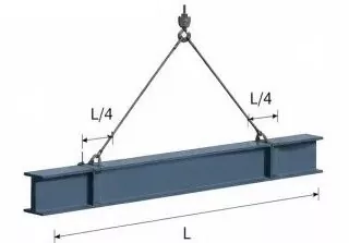
Member: Steel Beam H500×200×10×16, Length L = 12.0 m
Lifting Points: Set at L/4 from each end of the beam
Sling Angle: α ≈ 60°


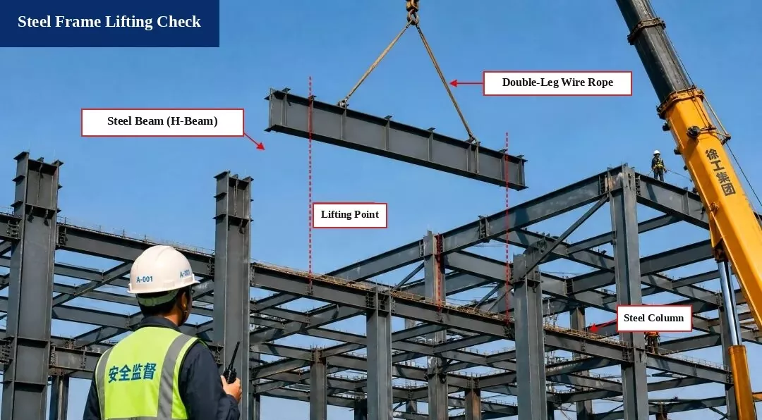
Extracted Photo Labels: Lifted Part: Steel Beam (H-Beam) | Lifting Sling: Double-Leg Wire Rope Sling | Lifting Point Position | Steel Frame Column | Safety Supervisor (Helmet A-001) | Crane: XCMG Group
Member: Steel Beam H500×200×10×16, Length L = 12.0 m
Lifting Points: Set at L/4 from each end of the beam
Sling Angle: α ≈ 60°
1. Self-Weight of Beam:
G = ρ × V = 78.5 kN/m³ × 0.212 m³/m × 12.0 m = 199.9 kN
2. Dynamic Load Factor: Take 1.1
3. Weight of Slings: Ignored (negligible)
4. Total Lifting Load:
P = G × 1.1 = 219.9 kN
5. Sling Tension (Balanced Load):
T = P / (2 × cos α) = 219.9 / (2 × cos 60°) = 219.9 kN
1. Sling Type: φ20 steel wire rope, breaking load Fb = 360 kN
2. Safety Factor (n):
n = Fb / T = 360 / 219.9 = 1.64 > 1.25
Meets standard requirements!
Check Conclusion:
The lifting operation is safe and meets code requirements.
• Code for Construction of Steel Structures (GB 50755-2012)
• Technical Code for Safety of Lifting and Hoisting in Construction (JGJ 276-2012)
1. Check the steel beam, wire ropes, and lifting tools before lifting to make sure they are safe and reliable.
2. Assign a dedicated person to direct the lifting process. No one may stand under the lifted beam.
3. Stop lifting work immediately when wind speed reaches Level 6 or higher.
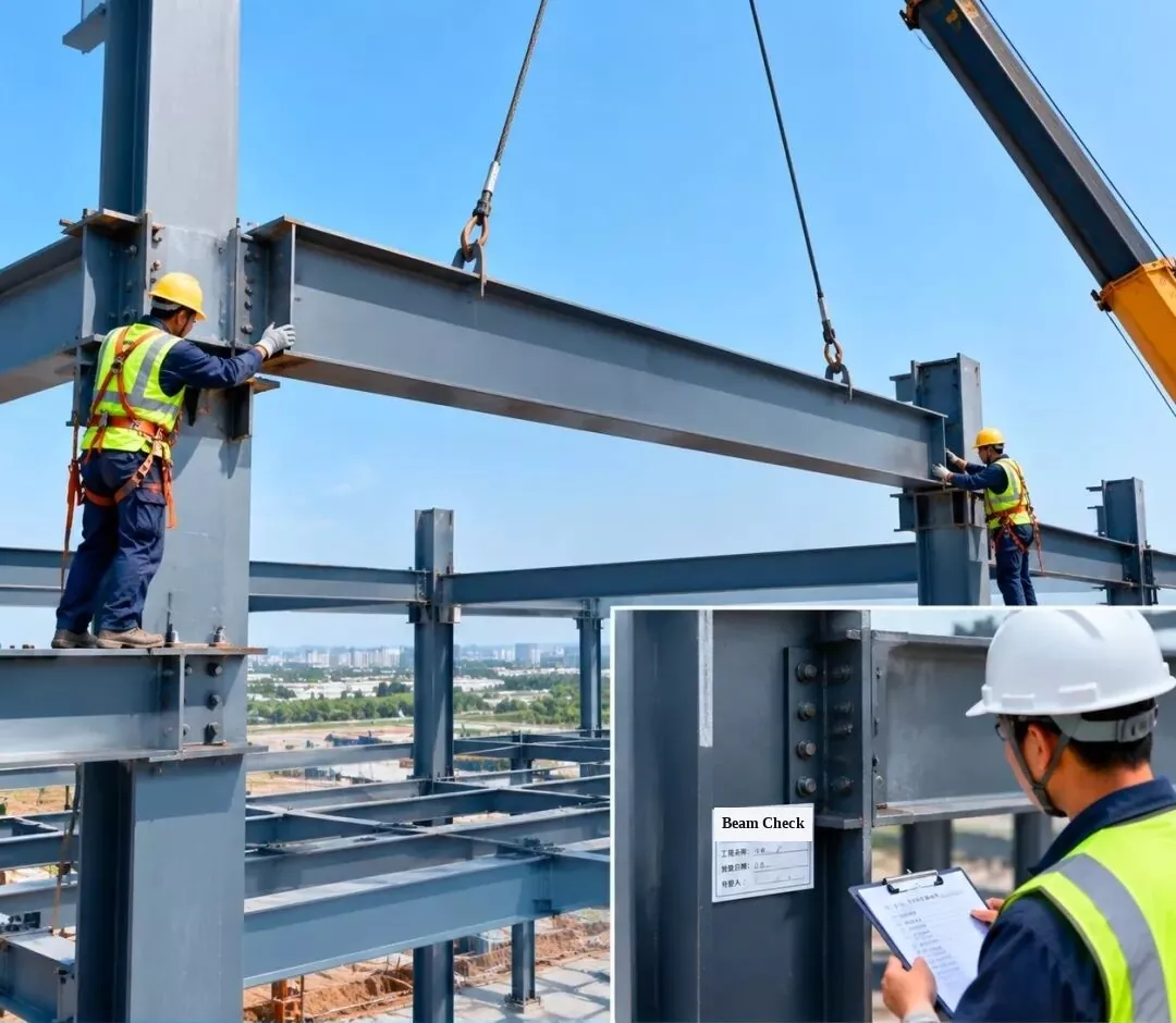
Lift the steel beam into its planned position, then inspect and approve the connection joints to make sure the installation quality meets design requirements.
[Inset Tag on Column: Steel Beam Installation Inspection | Project Name: Workshop #1 | Inspection Date | Inspector]
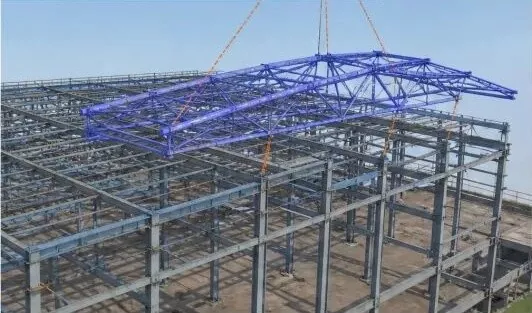 1. 3D BIM Simulation: Simulate the steel roof truss installation to improve the lifting plan and installation order.
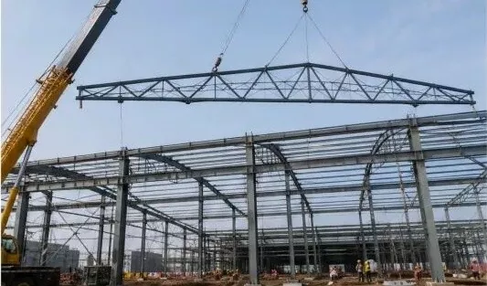 2. Roof Truss Lifting: Use a truck crane to lift the truss and place it slowly into position while keeping it balanced.
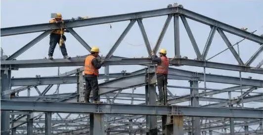 3. Positioning & Temporary Fixing: After the roof truss is in place, secure it temporarily and adjust its position and height (elevation).
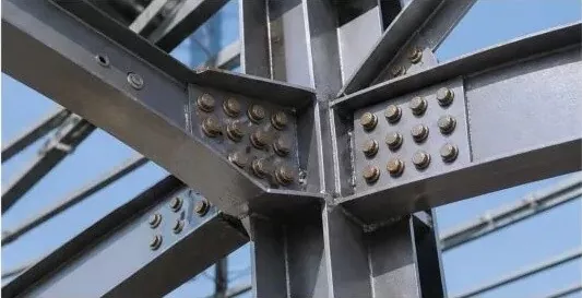 4. High-Strength Bolt Connection: Tighten the high-strength bolts according to the design rules to ensure a strong connection.
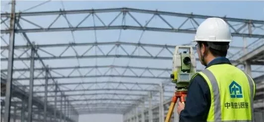 5. Installation Inspection: Check the truss height, span, bending (deflection), and vertical alignment to make sure they meet the code.
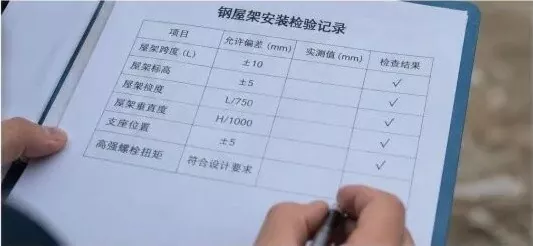 6. Inspection Record: After passing the inspection, complete the record form and move on to the next construction step.
| Inspection Item | Allowed Error (mm) | Measured Value (mm) | Check Result |
|---|---|---|---|
| Truss Span (L) | ±10 | — | √ (Pass) |
| Truss Height (Elevation) | ±5 | — | √ (Pass) |
| Truss Bending (Deflection) | L / 750 | — | √ (Pass) |
| Truss Vertical Alignment | H / 1000 | — | √ (Pass) |
| Support Position | ±5 | — | √ (Pass) |
| High-Strength Bolt Torque | Meets design requirements | — | √ (Pass) |
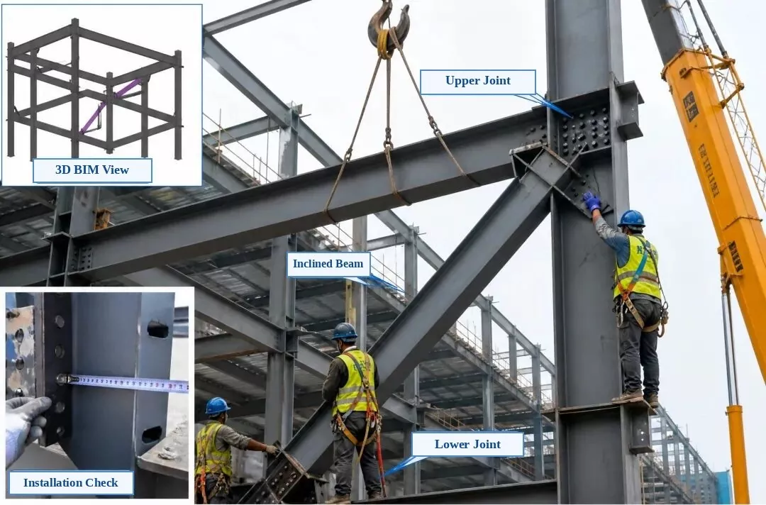
Extracted Photo Labels: Top-Left Inset: 3D BIM View | Bottom-Left Inset: Installation Check | Main Photo: Upper Connection Joint, Inclined Steel Beam (Diagonal Brace), Lower Connection Joint
1. Pre-Installation Check: Check the part number, size, bolt hole positions, and connection plate direction. Make sure the contact surfaces are flat, clean, and free of burrs or oil.
2. Lifting and Positioning: Use two lifting points to lift the inclined beam slowly into place. Fix it temporarily and make sure both the upper and lower joints line up accurately with the steel column and beam.
3. Alignment and Adjustment: Adjust the centerline position, height, and vertical alignment of the inclined beam to meet design requirements. Complete the permanent connection after alignment.
4. Connection Method: Connect with high-strength bolts. Tighten them evenly from the center outward to both sides as required by the design, and mark each bolt after final tightening passes inspection.
5. Installation Inspection: Check the centerline position, height, vertical alignment, plate contact tightness, and bolt tightening quality. Everything must meet the Code for Acceptance of Construction Quality of Steel Structures (GB 50205).
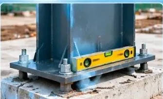
1. Foundation Check: Check whether the anchor bolt positions, foundation height, and foundation dimensions meet the design requirements.
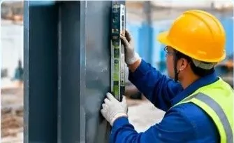
2. Vertical Alignment Check: Use a total station, laser plumb, or straightedge level to check how straight (vertical) the steel column stands.
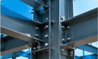
3. Connection Quality Check: Check whether the high-strength bolts, welds, and connection plates meet the standard requirements.
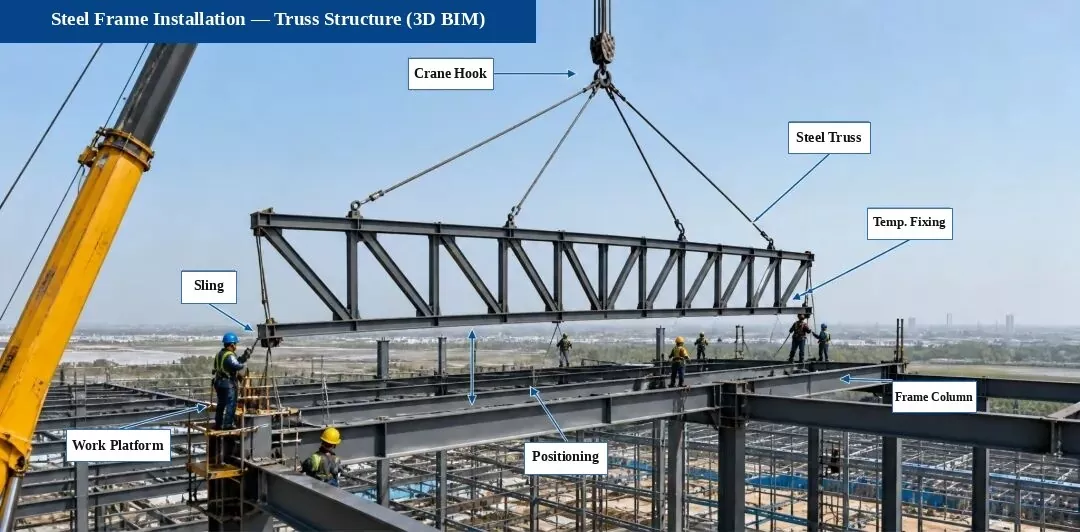
Extracted Photo Labels: Crane Hook | Steel Truss Structure | Temporary Fixing | Lifting Sling | High-Work Platform | Place in Position | Steel Frame Column
Installation Process Flow: Survey & Marking → Support Check → Lift & Place → Temporary Fixing → Alignment & Adjustment → High-Strength Bolt Connection → Welding (if required)
Key Installation Points: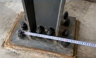
Check the positions and heights of support bolts, shim plates, and embedded parts to make sure they meet design requirements.
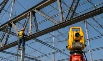
Use a total station to measure the centerline, height, and bending of the truss, and make alignment adjustments.
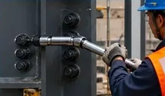
Check the number, size, and torque of the high-strength bolts, and re-test them as required by the code.
Note: The truss structure in this project is pre-assembled in the factory and lifted in sections on site to ensure accurate installation, quality, and safety.
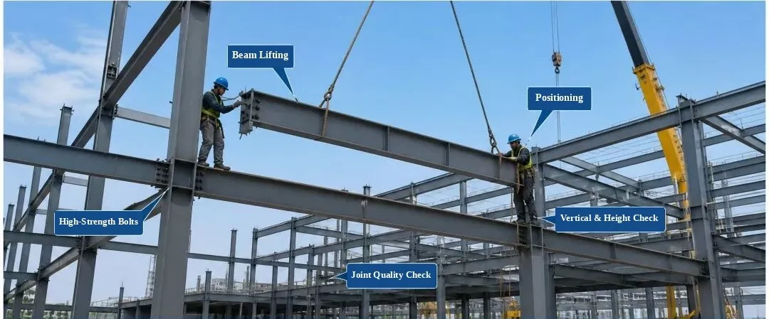
1. Incoming Part Check: Check the material quality, size, surface condition, and straightness. Install only after passing inspection.
2. Process Control: Control part positioning, height, vertical alignment, and bolt tightening during installation.
3. Inspection Items: Centerline position, height, vertical alignment, surface flatness, and bolt connection quality.
4. Quality Standard: Must meet the Code for Acceptance of Construction Quality of Steel Structures (GB 50205-2020).
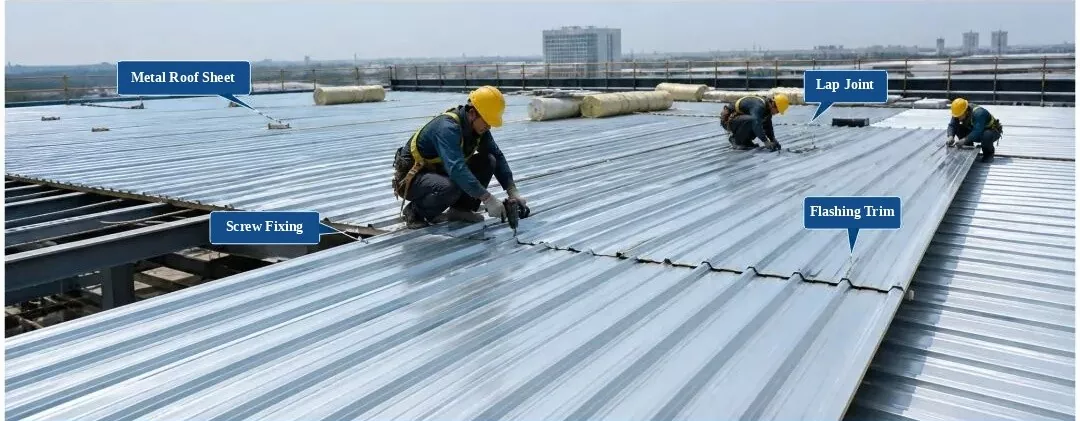
1. Material Check: Check the panel profile, thickness, coating, and color. Use only after passing inspection.
2. Installation Rules: Overlap the panels correctly and fix them firmly. Keep screw spacing within standard limits, with no missing or misplaced screws.
3. Inspection Items: Roof flatness, overlap width, fastening point spacing, and waterproofing details.
4. Quality Standard: Must meet the Technical Code for Metal Roof Engineering (GB 50345-2012).
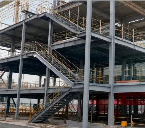 1. Completed Steel Stairs and Handrails (Site Photo)
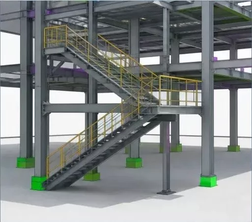 2. 3D BIM Model (Steel Stairs and Handrails)
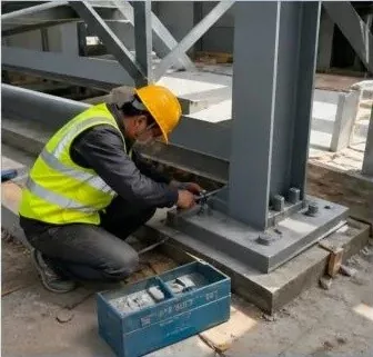 3. Steel Stair Installation (Site Work)
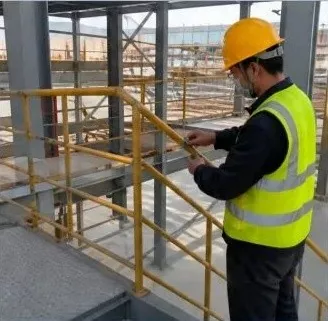 4. Handrail Installation (Site Work)
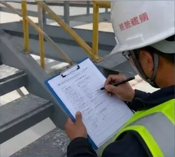 5. Installation Quality Inspection (Site Check)
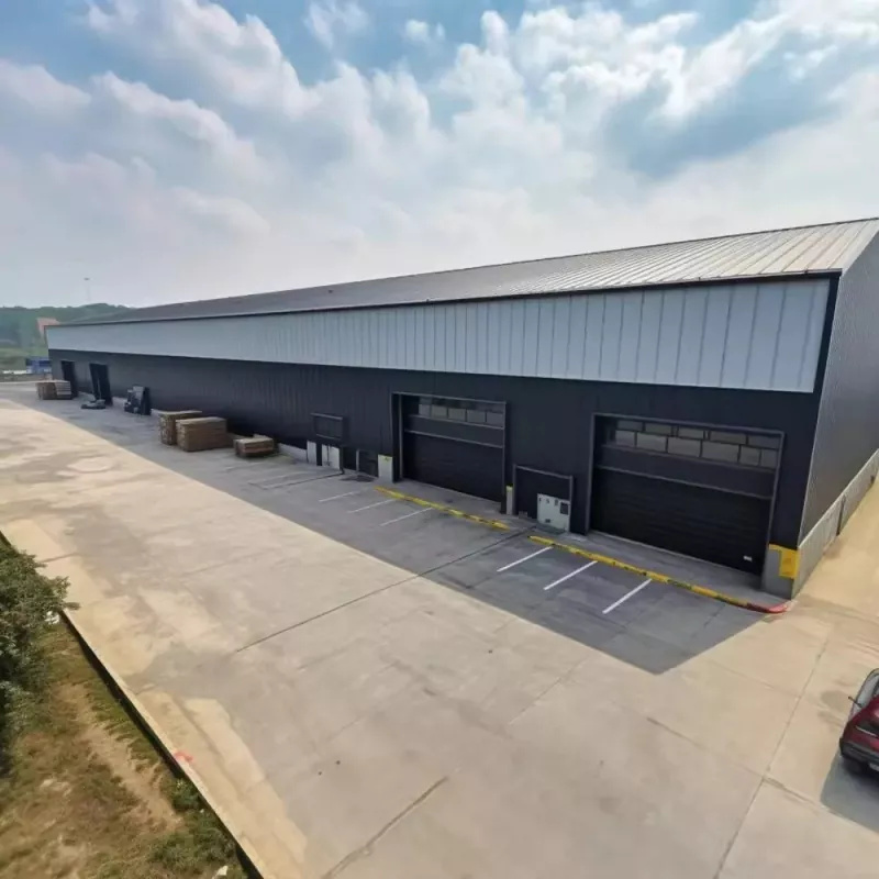
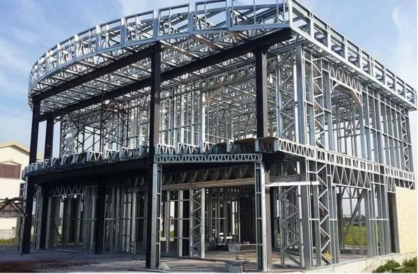
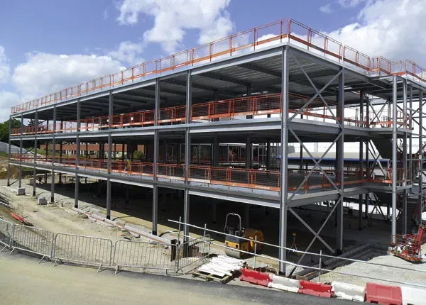
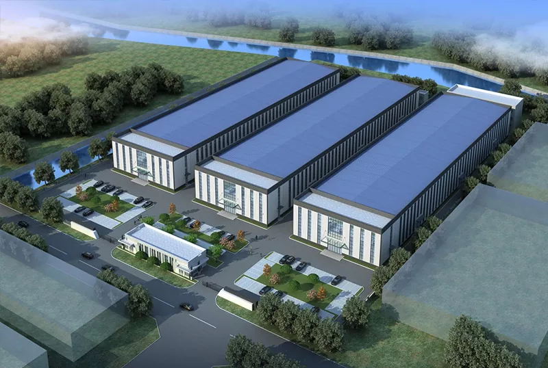
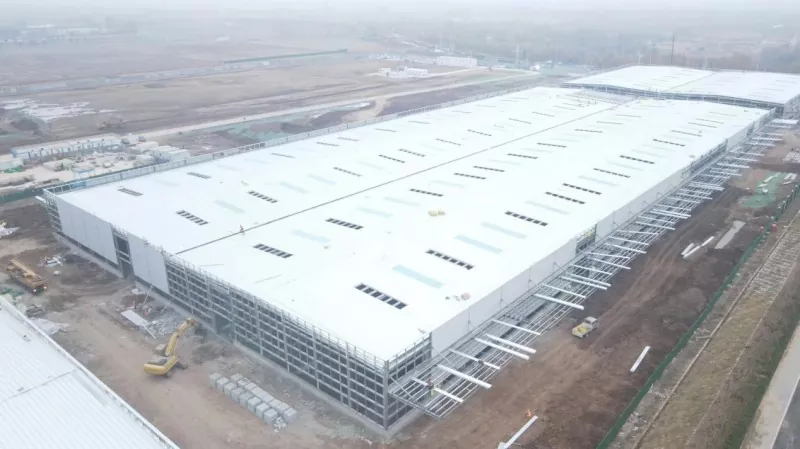
Steel structures are widely used in today's construction market to build building frames, and they will become the main choice for primary building structures in the future. Steel structures have many sub-categories, structure types, and component types. Based on the structural system, they are divided into four main types: portal frames, space grids, trusses, and frame structures.